
3 Subwoofer Box Terminal Options in 2026
As an Amazon Associate, this website earns from qualifying purchases.
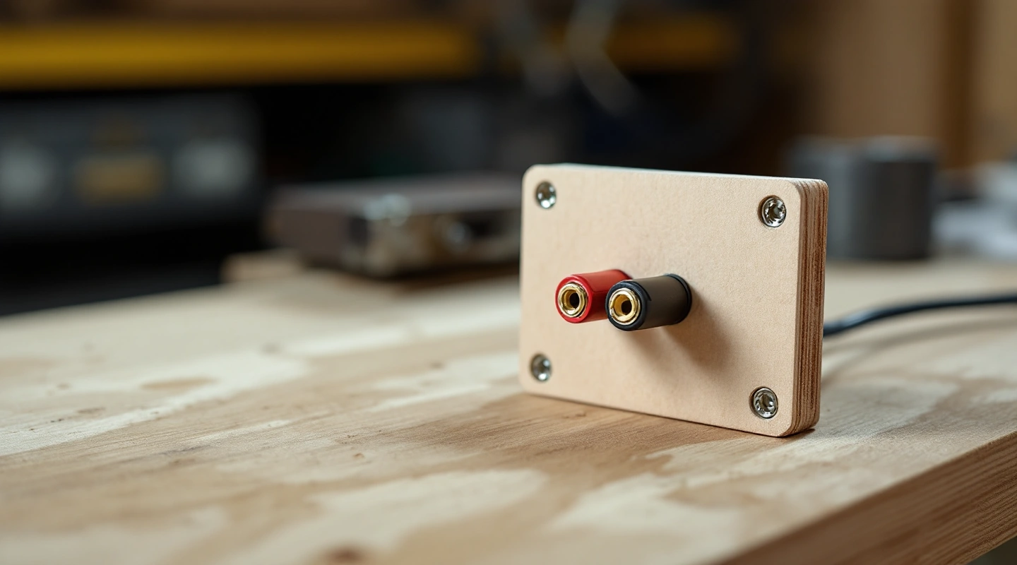
The short answer
Choose a subwoofer box terminal by wall thickness, cable access and sealing. Compare Dayton direct posts, a Parts Express spring cup and a Neutrik locking connector. Keep missing cutout, rear projection and electrical limits unresolved until confirmed.
Our top 3 picks
- 1Separate panel posts
 Dayton Audio BPA-38G binding posts
- One binding-post pair
- Listed panel range: 3/8 to 1 inch
- Knurled shaft resists rotation
- 2Spring-terminal cup
 Parts Express square spring terminal cup
- Spring-loaded pushbutton terminals
- Color-coded polarity marks
- Catalog wire capacity: up to 12 gauge
- 3Locking cable route
 Neutrik NL4MPXX chassis connectors, four pack
- Four chassis connectors in the listed pack
- Four-pole connection system
- Current NL4MPXX model; use its own drawing
#1. Dayton Audio BPA-38G: direct binding posts
Dayton Audio BPA-38G binding posts
Our verdict:
Separate panel posts
A direct-post option when the wall thickness and rear wiring space fit the drawing.
Keep in mind: Seal both mounting holes and check the nut, washer and wire clearance behind the panel.
View on Amazon- One binding-post pair
- Listed panel range: 3/8 to 1 inch
- Knurled shaft resists rotation
The BPA-38G pair is the direct-post route. Each post mounts through its own hole rather than a large recessed cup. That makes sense when the panel offers enough land for the posts and you can reach the internal nuts and leads during assembly.
The current catalog lists a panel-thickness range from 3/8 inch to 1 inch. Dayton's product page supplies the model and mechanical drawing. Use that drawing for the hole and hardware arrangement. The overall length of a threaded part is not the same as the usable thread behind your wall.
A direct post can avoid cutting a large cup hole, but it does not remove the need to seal the mounting. Follow the maker's mounting and hardware instructions. Keep the two conductors separate. The knurled shaft is there to resist turning. Do not rely on a loose wire to keep the rear hardware from moving.
Choose this pair if the wall thickness and rear access suit the build. Skip it when you cannot reach or inspect the inner connections. We found no basis here to assign a complete subwoofer-system power rating from the plating or the word heavy-duty. The electrical limits of the finished connection require evidence for the actual hardware and installation.
#2. Parts Express square cup: spring terminals
Parts Express square spring terminal cup
Our verdict:
Spring-terminal cup
A straightforward cup for bare wire when the cutout, rear space and wire size suit the build.
Keep in mind: Obtain the actual cutout and rear projection. The outside flange size is not a drilling template.
View on Amazon- Spring-loaded pushbutton terminals
- Color-coded polarity marks
- Catalog wire capacity: up to 12 gauge
This square cup uses spring-loaded pushbuttons with color-coded polarity marks. Its current catalog states a wire capacity up to 12 gauge and an outside square size of 2-3/16 inches. Those facts make it a different connection style from the separate binding posts.
The cup suits a layout where a small recessed connection is useful and the chosen bare wire fits the terminal. Verify that the spring grips the conductor rather than its insulation. Do not force an oversized wire into the opening or leave stray strands where they can bridge the terminals.
The catalog does not establish the exact cutout, rear projection, occupied volume or a complete electrical rating for this cup. We keep those as missing facts. Do not copy the cutout from a larger Parts Express cup whose flange looks similar. The manufacturer's terminal range contains several different shapes and sizes.
This is the quick bare-wire option, with a clear qualification limit: get the actual drawing and sealing details before cutting a finished wall. If the seller cannot supply them, choose a terminal with a complete drawing. A low part cost is not a reason to make an irreversible hole from an outside dimension.
#3. Neutrik NL4MPXX: a locking connector system
Neutrik NL4MPXX chassis connectors, four pack
Our verdict:
Locking cable route
A locking connector route when you can follow the current maker drawing and pin assignment.
Keep in mind: The chassis pack does not include the complete cable or prove an airtight enclosure seal.
View on Amazon- Four chassis connectors in the listed pack
- Four-pole connection system
- Current NL4MPXX model; use its own drawing
The NL4MPXX offers a locking cable connection. The selected listing is a four-pack of chassis connectors, not four complete cable assemblies. Match the current Neutrik NL4MPXX drawing and instructions to the exact part before planning the opening.
The model is a four-pole connector. That pole count describes available contacts, not the number of subwoofers it automatically wires. Write down which contact serves each conductor. Use the same assignment at both ends and confirm it before connecting the amplifier.
Neutrik's current page identifies the mounting form and flat-tab terminations. The catalog uses a broad solder-tab description. Check the maker's drawing for the hardware actually delivered rather than forcing the wrong quick-disconnect onto a tab. The plug, cable size and termination method must belong to the same connector system.
We do not call this chassis connector airtight. The current source does not establish that claim for the full installation. A flange gasket cannot by itself prove that no path exists through the connector body. If an airtight cavity depends on the connector, obtain the maker's sealing guidance or design a separate sealed terminal space.
Choose this route for a deliberate removable-cable design. Its trade-off is the extra system work: a mating plug, the correct cable, clear contact labels and a mounting seal. The older NL4MP-1 is discontinued, so its old specifications do not substitute for the current XX model.
Factors to consider when choosing a subwoofer box terminal
Start with access and the wire route
The right subwoofer box terminal must fit the wall and allow sound wiring. You also need access to inspect it and a clear sealing method. Decide whether the cable must detach often, whether you need bare-wire access and how much the external connection may protrude. These choices can eliminate a terminal before you compare its finish.
Draw the wire route on both sides of the enclosure wall. Outside, leave room for the chosen plug or banana connector and its cable bend. Inside, keep the lead away from the cone, basket, brace edges and vent path. A terminal that fits the wall can still put the wire in the driver's moving envelope.
For a sloped enclosure, check the rear projection where the terminal actually sits. The wedge planner can help with the shell geometry. Draw a section through the terminal and magnet, including any brace near them.
Distinguish flange, cutout and depth
The flange is the outside surface that covers the opening. The cutout is the hole needed to pass the rear body through the wall. Mounting depth includes the rear hardware and the space the connected lead needs. These dimensions answer different questions.
Do not trace the flange and cut on that line. That can leave no supporting land for the screws or gasket. Start from a model-specific drawing and confirm whether it shows a round hole, a square body, separate post holes or a shaped chassis opening. Print a template at the right scale only when the source supplies one.
Check fastener positions before cutting. A screw too close to the driver cutout or a panel edge can leave weak material between the holes. A screw behind a brace can become impossible to tighten later. Dry-fit the terminal while you still have access to the back of the wall.
Match the wall thickness
A part designed for a thin panel may not provide enough thread or body length for a thick baffle. A direct binding post with a stated thickness range still needs the correct washer and nut stack. A cup may need a recess, which changes the local wall thickness and support.
Measure the actual sheet. A nominal 18 mm panel is not exactly 3/4 inch, and a double baffle can exceed the range of hardware that fits a single sheet. The material guide explains why stock labels and actual cut dimensions should stay separate.
Do not leave out hardware that the maker requires just to gain thread. Follow its mounting order. Choose a part with the correct mounting range or change the mounting structure using a documented plan.
Keep electrical limits specific
Check the wire gauge, wire type, contact rating and joint method. The stated wire size tells you what fits the part. It does not prove that the whole circuit can carry any amp output with that wire. Check the cable length and the amp's guide too.
Gold plating does not set a current limit. A large post head does not show how thick the contact is inside. Do not join contacts in parallel unless the maker allows that use. Read the exact part's data. A rating for a similar part does not apply by default.
The terminal does not choose the driver's nominal load. The voice coils and their series or parallel wiring do that. A poor contact can add resistance. It cannot fix a coil circuit that puts the wrong load on the amp. Follow the driver's wiring diagram and the amp's load limits.
Make polarity easy to inspect
Choose a consistent positive and negative marking from the amplifier lead to the driver. Check the marks on the cup and on the driver; do not assume the red wire always reaches the expected contact inside a prewired box. Keep a clear connection record if you use a four-pole plug.
Disconnect power before a meter check. Follow the meter's guide to check the intended path and look for shorts. This can help find a wrong contact or a loose strand that bridges two wires. It is not a full safety check. You must still follow the amp's setup guide.
Label the removable lead if several cables use the same connector shell. Physical mating does not prove that two leads have the same contact assignment. This is especially relevant when a four-pole system shares space with two-conductor speaker wiring.
Seal each opening with the right method
Air can pass through a wall joint, a post hole or the part's body. Follow the sealing guide for each path. A flange gasket does not prove the body is closed. Glue around the flange cannot fix a loose contact inside it.
Use the correct gasket land and tighten fasteners as the maker directs. Check that carpet or a rough edge has not stopped the flange from seating. Keep adhesive and sealant out of moving spring mechanisms and contact surfaces. Let compatible joint materials cure before the enclosure is put into use.
The box sealing guide covers the wall seams and driver gasket too. Treat the enclosure as a system of joints. An excellent terminal mount cannot correct a leak elsewhere in the shell.
For a molded shell, include the terminal mount in the fiberglass plan before the layup fixes the wall shape. Leave room to reach and seal the connection.
Account for occupied volume
The part inside the cavity takes up airspace. Rear nuts, a cup body or a sealed pocket may matter in a small box. The outside flange and plug sit outside that space. Do not count them as an airspace loss just because they come with the part.
Use a maker drawing or a sound estimate for the part inside the box. State how you found that estimate. A block drawn around a hollow or curved part may count more solid space than the part uses. Label it as an estimate, not a measured fact from the maker.
The enclosure calculator has two separate checks for this part. Its solid volume goes in the airspace ledger. Its full shape can also be entered for the fit check. That shape helps find clashes with other parts. It does not tell you the exact solid volume on its own.
When the terminal volume is unknown, leave it unknown. The worksheet will show the incomplete airspace record. That is a more useful result than a precise-looking number produced by silently assigning zero to a real part.
Keep service work possible
Plan how you will reach the connections after the driver goes in. A cup can sometimes be removed from outside; separate posts may need access through the driver opening. Do not route a lead so tightly that removing the terminal pulls on the driver connection.
Provide strain relief where the connector instructions require it. External cable movement should not become a repeated pull on an unsupported internal joint. Keep enough service length to work on the part, while keeping loose loops out of the driver's moving space.
How we picked the subwoofer box terminals
The three picks serve different mounting and wiring needs. We read the Dayton and Neutrik maker pages for the mounting details. The Parts Express cup still needs a cutout size and rear depth. We have not tested these parts for sound, leaks, contact resistance or current limits.
The picks cover posts, spring contacts and a locking plug route. They do not share a proven current limit or seal rating. If a key limit is missing, choose a part with better data. Do not assume the unknown value is the one that makes your plan work.
Subwoofer box terminal verdict
Choose a subwoofer box terminal from its mounting data and the wire route. Use the BPA-38G pair when its panel range and rear access suit the build. Choose the spring cup only after its missing mounting facts are resolved. Choose the NL4MPXX when a complete locking-cable plan is useful and the sealing method is established. Keep the cutout drawing, wiring record and occupied-volume ledger together with the construction plan.
Frequently asked questions
Does a terminal change the driver impedance?
It does not select the nominal driver load. Voice-coil wiring establishes that load; loose or poor contacts can add unwanted resistance.
Can I cut the hole from the outside flange size?
No. Use the exact model's cutout drawing and leave the supporting flange and gasket land intact.
Is the NL4MPXX an airtight terminal?
That is not established by the current source used here. Confirm the full sealing arrangement rather than borrowing an older connector's claim.
Last updated