
Ports and tuning
How to Tune a Subwoofer Box
Last updated
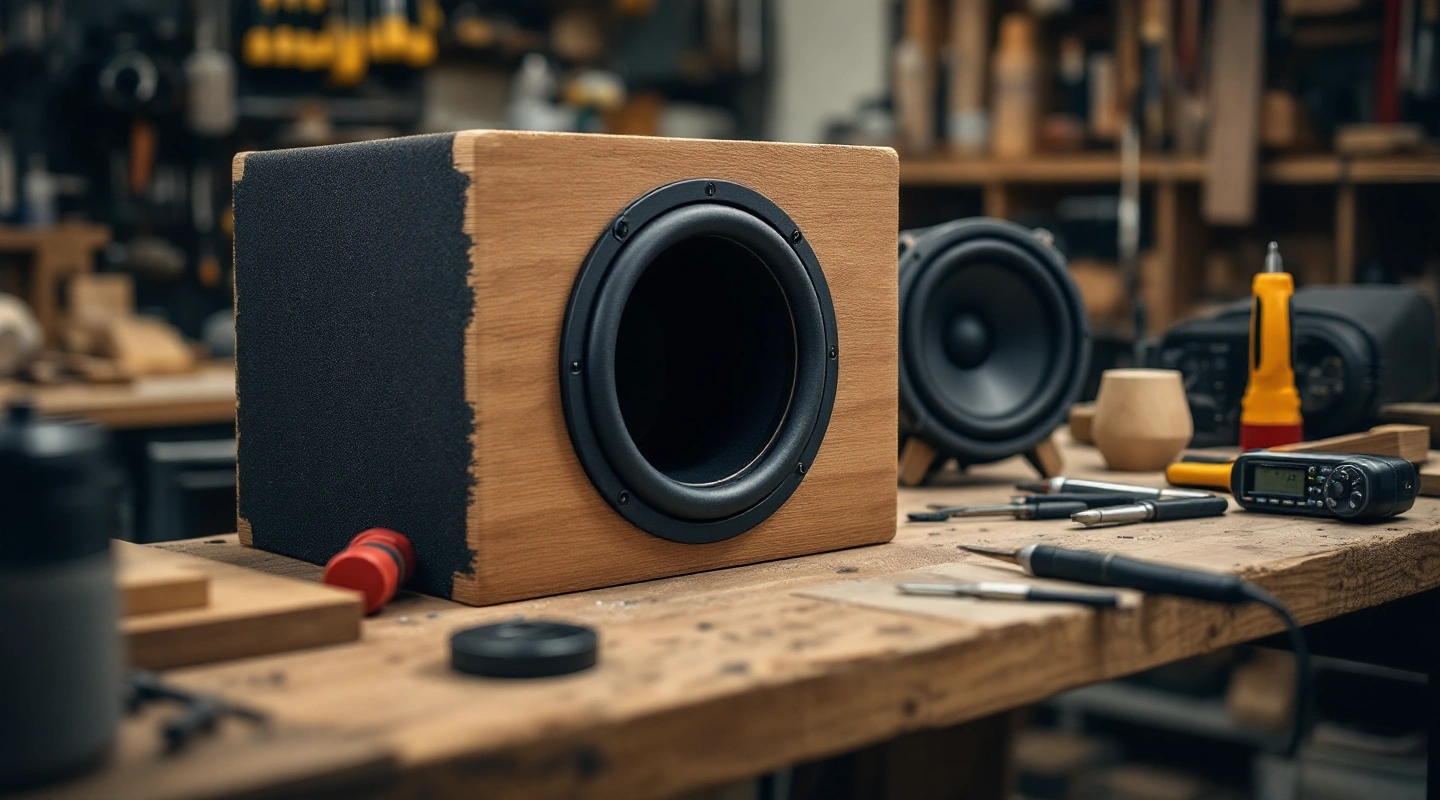
Learning how to tune a subwoofer box starts with the exact driver's stated vented design. Use true net airspace and effective vent length in the math. Then check the actual cabinet. Keep the chosen alignment separate from measured tuning. An amplifier bass knob does not change the physical vent's tuning frequency.
Box tuning Fb depends on net cavity, clear port area and effective length. A longer effective vent lowers the estimate when the other inputs stay fixed. Keep the end correction stated and check occupied space again when the physical port changes. A measured tuning check needs suitable calibrated low-level equipment; a calculation alone is not a measurement or a safe-power rating.
On this page
1. Choose the stated alignment
Copy the complete driver model and source revision. Read its vented target, port example and operating limits. A preferred musical style is not enough to choose a frequency without a suitable alignment. This site does not generate a fixed vented recipe from Fs or Qts alone.
Published tuning is a source fact. Computed tuning is an estimate under the equation's assumptions. Measured tuning is an observed result from a stated setup. Keep those three labels separate, even when their numbers are close.
The JL worked guide keeps the maker's figures beside the ideal model's results. It does not force every equation to match. The CompR guide explains a different volume convention. Settle which convention applies before using an acoustic formula.
2. Measure the subwoofer box and vent
Measure the finished inside cavity. Subtract the space occupied by the driver and other fitted parts, including the duct. For a slot, count duct air and its inside partitions. Do not subtract shared cabinet walls a second time.
Measure clear inside diameter or clear slot section. Record physical length and the parts of that length inside the cavity, through the baffle and outside the box. Keep the vent's opening clearances in the fit drawing. A restricted inlet is not the ideal open end assumed by a simple model.
The port calculator handles matching ports in one chamber. Each must have the same section and length. A duct that changes section needs another model. Unequal vents cannot be treated as one average tube.
3. Work out and invert the result
The rough relation from UNSW's Helmholtz explanation is:
Fb = c/(2π) × √(Atotal/(Vnet × Leff))
Use meters, square meters and cubic meters with sound speed in meters per second. Effective length is Leff = Lphysical + total end correction. To solve physical length, rearrange it as:
Lphysical = c²Atotal/((2πFb)²Vnet) − total end correction
Compute with full precision. After finding a length, put it back into the frequency equation. The inverse should return the target within numerical rounding. This catches an equation or conversion error. It does not validate the chosen end correction against a real port.
A round-port arithmetic example
Take true net volume 1.750 cubic feet and one 3-inch inside-diameter tube. Set the target to 26 Hz and sound speed to 343 meters per second. Assume one baffled and one free opening. That rough model gives a total end correction of 1.45 times the tube radius.
Clear area is 7.068583 square inches. The computed effective length is 15.972209 inches, correction is 2.175 inches, and physical length is 13.797209 inches. Substituting those values back gives 26 Hz before display rounding.
These outputs use a rough model of the port ends. Keep the maker's 14-inch vent example labelled as published. The JL manual lists that physical length with its target. Different builds and end treatments can give different results. The ideal estimate need not match the published length exactly.
Suppose the example tube has outside diameter 3.25 inches. It passes through a 0.75-inch baffle with no outside protrusion. About 13.047209 inches lies inside the cavity. Use that length and the outside cross section for occupied volume. Use the full physical length plus its end correction for acoustics.
End-correction limits
The round presets use rough coefficients derived from the source's discussion: 0.85 times radius for a baffled circular opening and 0.6 times radius for the free-end rough model. Both baffled gives 1.7 times radius; one of each gives 1.45. The layout must match the selected assumption.
The source warns that a non-round opening does not share the same end effect as a circle of equal area. A slot, flare or fold needs its own documented treatment or an explicit assumed correction. A circle of equal area is not a verified shortcut for a slot.
Changing sound speed also changes the estimate. The default 343 meters per second is an editable math assumption from the source's worked example. It is not a measurement of your box's air temperature or conditions.
4. Check the finished subwoofer box tuning
First verify the built sizes and seals. An incorrect vent length, unexpected intrusion or leak can make the real box differ from the drawing. Measure what exists before adjusting an equation to make it agree with a symptom.
Use low-level impedance equipment to check Fb. Follow its setup and calibration steps. The Dayton DATS manual shows vented-box curves. The REW instructions explain its test circuit and calibration. Read the procedure for the equipment you will use.
A conventional vented impedance curve has two low-frequency peaks with a minimum between them near tuning. Read the curve in the context of the stated setup and box losses. Do not choose whichever peak happens to match the frequency you wanted.
Disconnect the external amplifier as the measurement instructions require. Do not attach an unknown powered signal to a test interface. Keep the raw sweep, setup and date with the plan if a measurement is made. This guide reports no sweep or physical test.
5. Revise the vent as a complete design
At fixed net volume and area, longer effective length lowers computed Fb. At fixed length and area, a smaller net cavity raises it. Those relationships help explain a change, but a real modification can alter several inputs at once.
Lengthening an inside duct adds space taken up and reduces net cavity in a fixed shell. Recompute both rather than using the old net value. Increasing area for a restriction or noise concern may need a longer vent to keep tuning, which can also require a larger shell.
State how the model treats a fold or flare. Follow the ported build sequence to check the route before assembly. A positive calculated length can still be too long for the shell. Leave room for the required opening clearance as well.
Keep amplifier controls separate
Gain, equalization and filter settings act on the signal. They do not lengthen a physical duct or change the shell's geometric cavity. A response peak heard in the vehicle can also include cabin effects, which this small-signal vent equation does not model.
Follow the exact driver's operating and filtering guidance. KICKER's box explanation discusses behavior below tuning. A lower Fb should never be presented as built-in permission for more power or more cone travel.
FAQ
Does the amplifier frequency knob tune the box?
It changes the signal treatment according to the amplifier's design. It does not change the physical port dimensions. Read the amplifier manual for its crossover and equalization controls. Use the stated box layout or a suitable measurement method for Fb. A listening impression alone does not establish box tuning.
Does a longer port lower tuning?
With net volume and clear area fixed, a longer effective vent lowers the ideal tuning estimate. But a real shell has fixed outside walls. Extra port length takes up more of its cavity. Update both the net volume and vent length. Then check the whole route again.
Can I use the same correction for a slot and round tube?
Not as a verified general rule. Non-round end effects differ, and flares or folds add further layout limits. Use a stated correction for the actual vent, or label an entered assumption as rough. The calculator does not silently convert a slot into a circle and claim equivalent end behavior.
Is measured tuning the same as F3?
No. Fb is the vented alignment's tuning frequency. F3 is the frequency where response falls 3 dB below a stated reference level. They can differ. Keep the maker's labels intact, and do not rename an impedance feature as a response cutoff. This layout calculator does not produce a measured response curve.
Verdict
To tune a subwoofer box, keep the source alignment beside the full layout. Record measured evidence separately. Calculate length and check it with the inverse equation before inspecting the actual build. Save the assumptions beside the result so a later change can be checked in the same way.