
Fit and worked designs
KICKER Subwoofer Box Design
Last updated
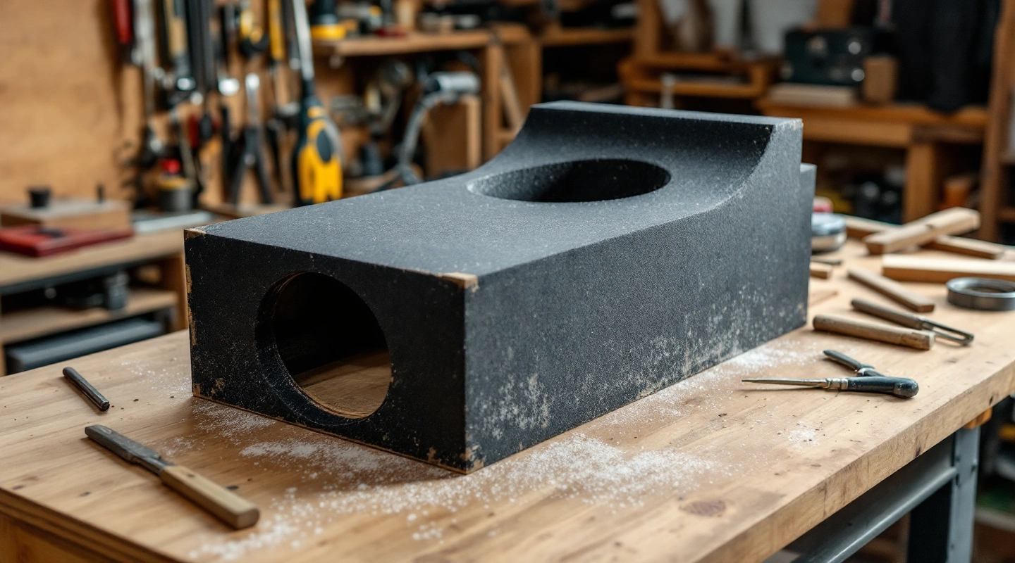
A KICKER subwoofer box design needs the exact series and manual generation. This guide uses the 2021 CompR revision C document. Its target already includes woofer displacement. For a vented build, add the port's occupied volume. Treating the base target as true net airspace would count the driver twice.
Keep the CompR manual's included-driver convention. Add the port envelope and any extra parts the chosen plan does not allow for. Do not invent a driver-displacement figure or add the driver a second time. You can still check the shell target when that deduction is unknown, but true net airspace and calculated tuning remain incomplete.
On this page
Match the KICKER box design to the 48CWR model
The source is the 2021 CompR manual, revision C. It covers the listed 48CWR8, 10, 12 and 15 variants. Check the complete model code on your driver, including its impedance variant, against the document.
Do not borrow a box table from an older CompR generation or another KICKER series. A brand name does not prove that the parameters match. This guide makes no current-sales or stock claim for the manual's models.
The two-page manual contains fit data, sealed ranges and vented examples. Read each table header with its volume note. A cubic-foot value copied alone loses the definition needed for a correct shell calculation.
Read the included-driver convention
The manual's volume figures include woofer displacement. A stated vented example then adds port displacement to the stated box volume. This means the base figure is not true acoustic net airspace after every part is installed.
For the CWR12, the minimum vented base is 1.75 cubic feet. Use that as an included-driver, port-excluded target. List any braces or terminal parts beyond the source plan's allowances as extra deductions. Do not assume the base target already includes them.
The model reference table labels this volume basis. The JL worked guide uses a true-net target. Its ledger is different. Read those definitions before comparing the cubic-foot numbers.
Work through the CWR12 port envelope
The manual's isolated-duct example uses a clear section 12.5 × 2.5 inches and length 20 inches. With its stated 0.75-inch duct-wall assumption, the outside section becomes 14 × 4 inches. Multiply by length and divide by 1728.
Vport = 14 × 4 × 20 / 1728 = 0.648148 cubic feet
Add that to the 1.75 base. The required gross cavity before any extra intrusions is 2.398148 cubic feet. The source prints the rounded math as about 0.65 plus 1.75, giving 2.4. The unrounded result checks the same arithmetic.
This formula describes that isolated rectangular duct envelope. It is not a rule to add two wall thicknesses around a slot that shares cabinet walls. Shared shell material has already been removed when working out the cavity. Count inside partition material and duct air once in that case.
Check a fresh box design without inventing airspace
Suppose you choose an outside width of 30 inches and height of 16 inches, with 0.75-inch shell walls. Inside width and height are 28.5 and 14.5. A cavity of 2.398148 cubic feet needs about 11.527828 inches outside depth, before any extra brace or terminal allowance.
That calculation sizes a shell under the source example's volume convention. A 20-inch duct cannot run straight along that much shorter depth. A complete design needs a documented route with clearance checks. The arithmetic alone is not a finished physical plan.
If driver volume is missing, enter a known physical port length in the box planner. It can compare the included-driver target. It keeps that comparison separate from true net cavity. Net cavity and calculated tuning stay unknown until you know the driver deduction.
Separate the manual target from net airspace
The manual gives a box target, but it does not supply the occupied driver volume used in this reference. Do not infer that quantity from nominal cone size or swept volume Vd. Leave it unknown until a physical-displacement source supplies it.
Qts and Qtp name different parameters. Copy Qts from the exact model's sheet for the sealed calculator. Check the label as well as the number. Do not substitute a nearby value marked Qtp.
A manual plan and an ideal model answer different questions. Label each one. These checks confirm the volume ledger and its math. They do not model cone travel. They cannot establish maximum clean output.
Check fit before cutting
Use the source's frame size, cutout and mounting depth for the exact driver row. Plot the terminal location and motor envelope. Extra baffle layers change the mounting plane and cavity, so update both checks when adding them.
Keep the vent inlet clear of braces and nearby panels according to the chosen documentation. A path that fits on a top view may collide with the motor in side view. Follow the ported construction sequence to keep all three views tied to the ledger.
FAQ
Should I add the driver to the CompR target?
Not again for this manual's convention. The target already includes it. Add the port and any extra deductions that the source plan does not include. Keep the convention with the number when moving it into a calculator. Otherwise a generic net-volume rule could add the driver a second time.
Is 2.4 cubic feet the true net volume in the example?
No. It is the rounded gross cavity after the example port envelope is added to the included-driver base. Finding true net airspace needs the actual driver deduction and other installed parts. The unrounded gross result is about 2.398148 cubic feet before separately added braces or terminal parts.
Can I use the isolated-duct formula for a shared-wall slot?
Do not apply it unchanged. A shared cabinet wall is already part of the shell, so subtracting its volume again would double-count material. Work out the clear duct air and the actual inside partition union. Keep those sizes attached to a section drawing of the final route.
Does this example check a finished box layout?
It checks the source's volume arithmetic and convention. It does not prove that the duct clears the driver or other parts inside the chosen shell. A complete plan needs each envelope drawn with its required clearance. This page makes no physical-build or listening-test claim.
Verdict
A KICKER subwoofer box design needs the exact model and manual beside its volume convention. Verify the vent's real envelope and fit before using the cavity math as a cut sheet.